The lookAt function is interesting. But have you ever wondered how it works and how we can hand-make one?
Matrix Multiplication
To understand how it works, we must first take a look at matrix multiplication. For a 3x3 matrix \(A\), when we apply it to a vector, this is what happens:
\[Ax = \begin{bmatrix} A_{00} & A_{01} & A_{02} \\ A_{10} & A_{11} & A_{12} \\ A_{20} & A_{21} & A_{22} \end{bmatrix} \begin{bmatrix} x_0 \\ x_1 \\ x_2 \end{bmatrix} = x_0 A_{*0} + x_1 A_{*1} + x_2 A_{*2}\]And since matrix multiplications can always only be linear transformations for its own dimension, (otherwise it wouldn’t be called linear algebra,) we know that \(x\) can only be scaled or rotated. Three new axes are defined, namely the three columns of A: \(A_{*0}, A_{*1}, \text{and } A_{*2}\). And \(x\) is transported into a new space defined by the said three axes.
LookAt in Raymarching & Raytracing
If we look at the lookAt matrix (ha!) without the fourth column & row, as is evident in most Shadertoy shaders, (such as mine), you will notice that it is indeed correct. lookAt in the particular example I listed is comprised of three vectors, and a homogeneous vector, which if you ignore, is just the right vector, up vector, and the front vector of the camera, which forms the normal x, y, and z axes of a space.
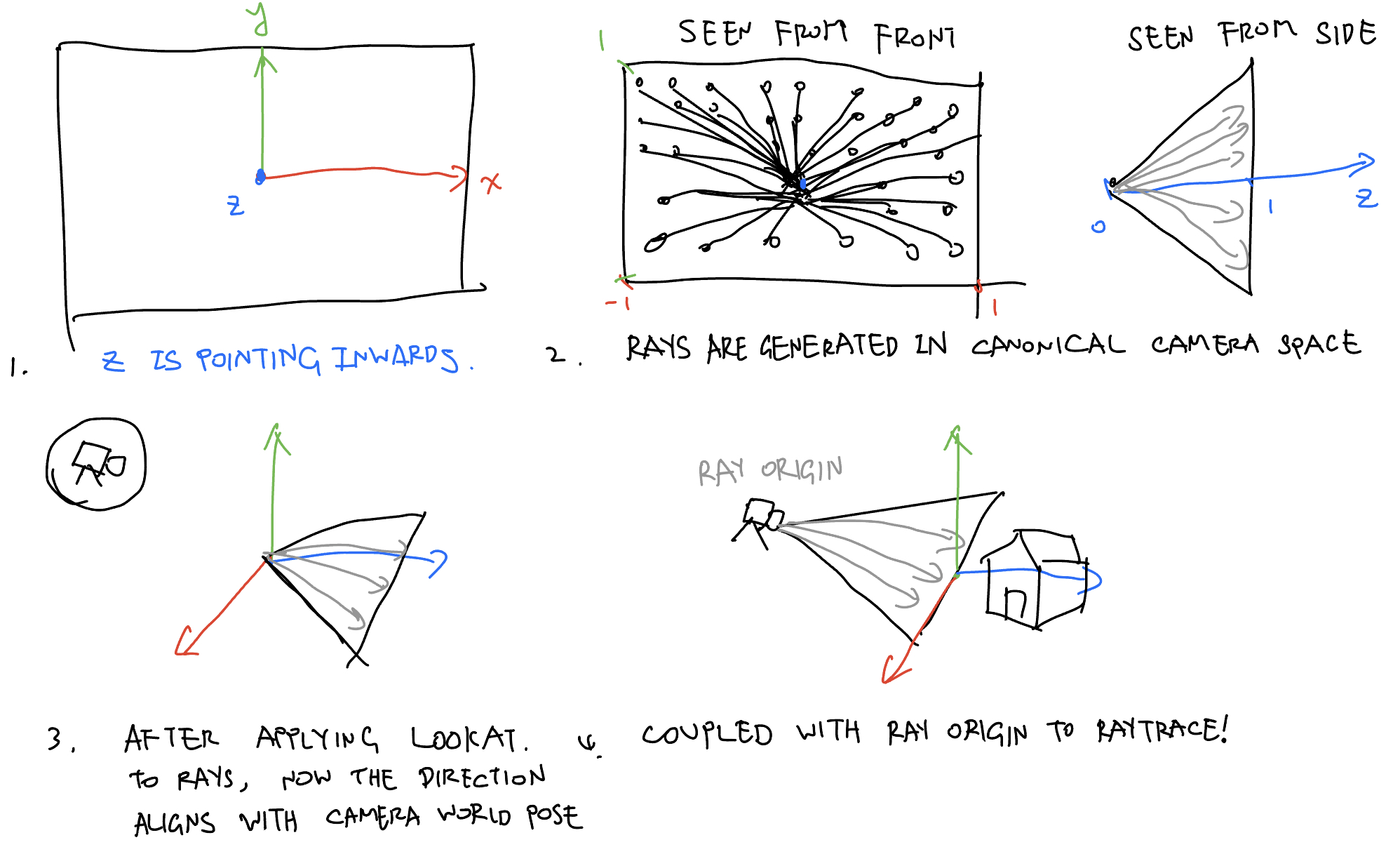
Since all the right, up, and front vectors are normalized, and are perpendicular to each other, that means all points from the original world space won’t scale - that is, all points will still have the same distance from origin. This means all points are only ever rotated. lookAt can thus be understood as a simple rotation matrix in raymarching code, rotating the rays’ direction from canonical camera space to world space. Which, when combined with ray origin, can be used to march rays along the world. Hopefully this hand-drawn illustration (by me!) can give you an intuitive idea:
LookAt in Rasterization
But is this what happens in rasterization? Close, but no. Why? Since OpenGL, or any other rasterizer, only ever rasterizes triangles drawn in \(\begin{bmatrix}x\\ y\end{bmatrix} \in [-1, 1]\), instead of rays, we are actually rotating the vertices into the OpenGL Normalized Device Coordinate (NDC) according to where the camera is facing, so that OpenGL can render it. As a result, the lookAt matrix in rasterization is the inverse of a raymarching/raytracing lookAt matrix. Luckily, since it is a simple orthonormal rotation matrix, simply transposing the matrix \(A^T\) is suffice.
Homogeneous Coordinate
Homogeneous coordinate is not needed in raymarching & raytracing, because rays are traced using the famous \(r(t) = o + td\) equation. Rays are generated & rotated according to where the camera is facing, then traced by plugging the ray direction \(d\) into the equation. When the camera translates, we just need to update the \(o\) term, the \(d\) need not be changed. In rasterization however, it’s the vertices being transformed, not the camera rays; when the camera moves, it’s actually the world that is moving. We need to use homogeneous coordinate to enable the translation of triangles, which is the basis of vertices, which is the basis of the entire scene.
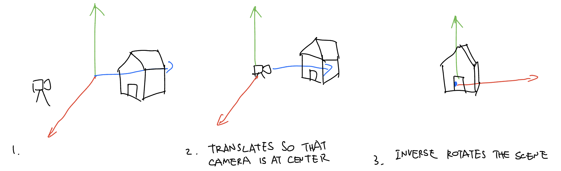
First, camera has to move back to the center of the world. Since in rasterization the camera doesn’t move, and instead the world moves around the camera, we apply the inverse translation of the camera eye position, thus forming the full 4x4 lookAt, or view matrix:
To translate this math equation back to English language, since we apply this view matrix to every vertex in the scene, we first translate it back to a space where camera is at the center of the world, then rotate it so that we are in canonical camera space. To understand it intuitively, here’s my hand-drawn illustration:
Perspective Matrix
Of course, only having the lookAt matrix is not enough (at least in rasterization) - things need to appear smaller when they are far away. Since OpenGL, or any graphics library for that matter, is only a 2D triangle drawing-and-shading library at the end of the day, we have to make them smaller ourselves. And here’s where the perspective projection matrix comes in handy. We are not covering it here - but a simple, intuitive idea would be multiplying all vertices’s xy components by their inverse z values so that far triangles with a large z appears smaller, while close up triangles appears larger. Check out Scratchapixel’s perspective and orthographic projection matrix article for more detail on them.
Further Readings
You can learn more about the lookAt matrix at Scratchapixel (which recently has a new version!) and LearnOpenGL, both of which are excellent learning resources.
Comments