Today, we’ll be talking about micro-meshes. The explanation will be high-level and incomplete because I am still in the course of understanding as well. Micro-mesh as a concept is proposed by NVIDIA, and promises three things, basically:
- Decreased mesh size
- Intrinsic LoD
- Fast
To quote from NVIDIA: “this technology efficiently stores opacity and displacement and allows assets to be used in their full fidelity, directly rasterized or ray traced.”
So how does that work? Let’s take a look!
Why Use Micro-Mesh?
Nowadays some scenes simply have way too many triangles. This number of triangles is simply unimaginable in the past. Our dear Sponza scene already has 262k triangles; the example scene Rungholt in tinyobjloader has over 6M triangles; and highly detailed, scanned stuffs (humans, buildings, etc.) are even more unhinged: scanned human from HumanDataset has a crazy 50M+ polycount. With huge amount of information comes huge file size. Assuming a polygon is a triangle, with position, normal and texture coordinate data, the raw, binary data already takes up at least 457M, textures notwithstanding. So, here comes the problem: is there a better way to store these meshes?
Micro-Mesh
Enter micro-mesh. Micro-meshes are basically low fidelity meshes, with a low polycount. Besides the original mesh structures however, A height map-like structure is also stored in the micro-mesh. When the micro-mesh is to be rendered, it goes over a tessellation stage which tessellates the original, low-res mesh. The vertices of that tessellation mesh are then displaced by the corresponding height in the height map by some direction to form the final high-resolution mesh. The high-res mesh is then rendered on screen, be it raytraced or rasterized.
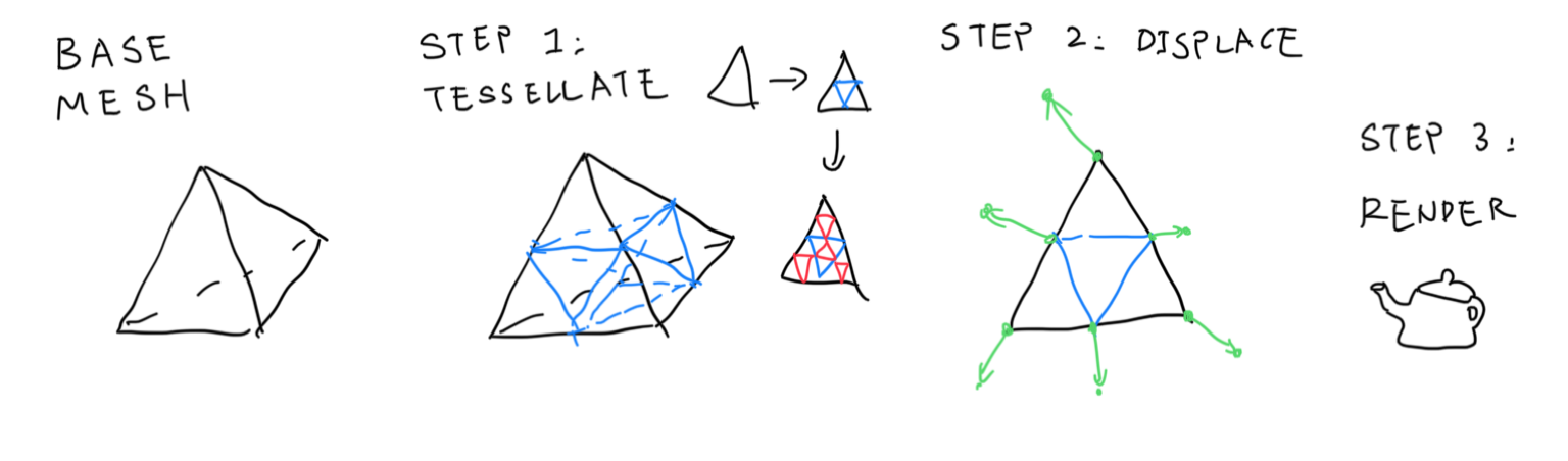
Base Mesh
More specifically, the low-res mesh is called the “base mesh”. Besides the regular mesh stuffs, the base mesh also stores “displacement direction” per-vertex, so that we know what direction to move toward to while displacing. “Tessellation level” is stored per-face, so that each triangle can be tessellated up to a certain level individually. This is useful because small triangles don’t really require that much tessellation; in comparison, large triangles can and will hold more details.
The tessellated mesh is called “\(\mu-mesh\)”, or micro-mesh. Tessellated triangles are called “micro triangles”, or \(\mu\)-triangles. Tessellated vertices are called \(\mu\)-vertices. For a face whose tessellation level is 0, there are only one \(\mu\)-triangle making up the whole thing; level 1 tessellation means 4 triangles, and so on.
\[\text{number of } \mu \text{ triangles} = 4^{\text{tessellation level}}\]Micromap
The Micromap is the data structure to store the “height map-like thing” mentioned above. It is stored in the barycentric data format, or .bary file. Micromap stores per-\(\mu\) vertex data for a micro-mesh. I highly recommend you to check out this slide to understand how micromap works. In a nutshell, micromap is a data format that is very suitable for storing subdivision vertices. Let’s take a look at the underlying principle of traversing a recursively subdividing triangle, the bird curve:
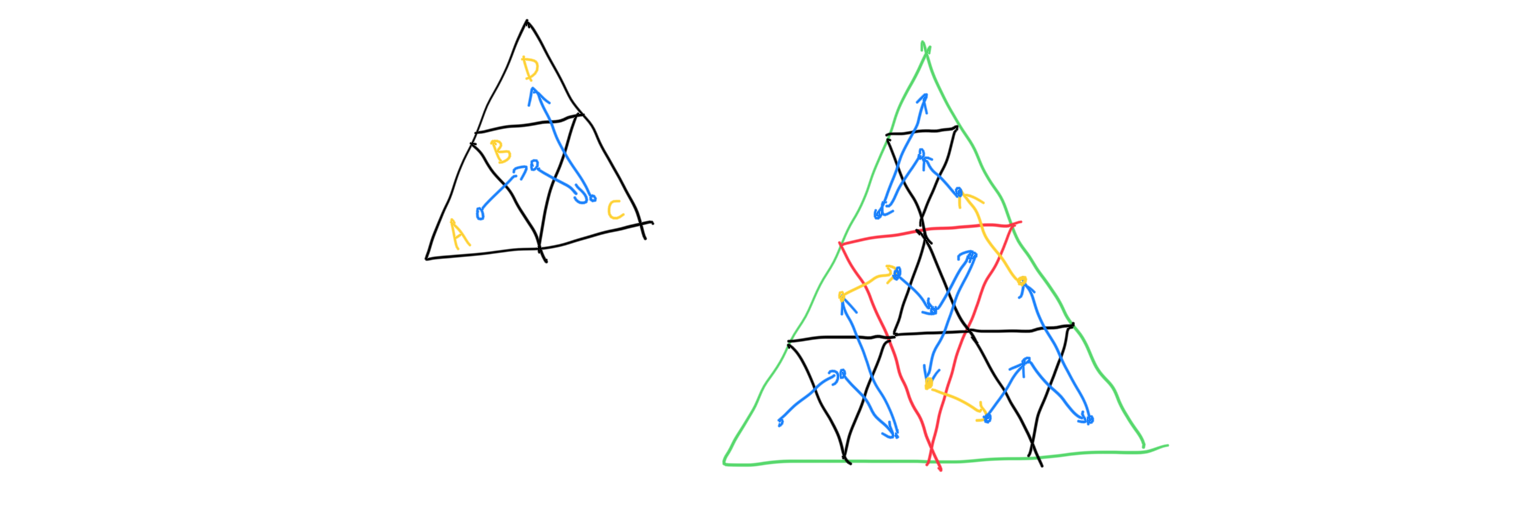
Did you notice the recursive nature of the bird curve? In the non-subdivided version, our visit order is A -> B -> C -> D. In the subdivided version, our visit order is still A -> B -> C -> D, but now we visit every triangle within them before jumping onto another triangle. In the mean time, the traversal order of B and D are a mirrored version of A and C, because we have entered the triangle from the other side. With this knowledge in mind, given a subdivided \mu-triangle, we can locate the corresponding data stored within the micromap extremely quick. The micromap’s indices is as such:

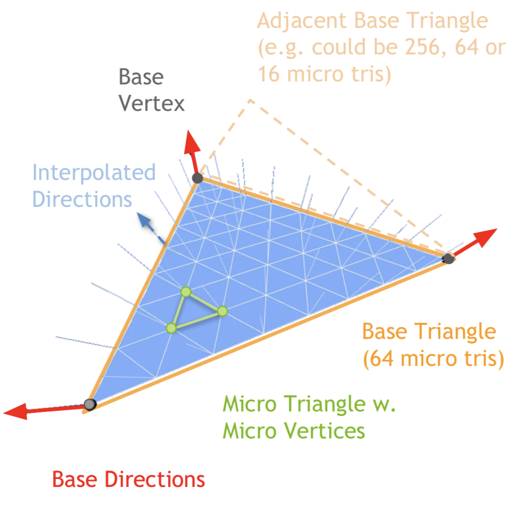
After tessellation and displacement data retrieval, the subdivided vertex is displaced along some defined direction. Since only the base mesh store the displacement direction, it is linearly interpolated across the whole subdivided triangle, forming the high-res mesh. Image cropped from the slide mentioned above.
During runtime, the micromap can be uploaded directly to NVIDIA GPUs (40 series only?), making the whole process very fast. In addition, the micromap can be block-compressed, leading to a decreased mesh size. As tessellation happens during rendering, we can just tessellate less for far away objects, leading to free & easy LoD implementation. So that’s pretty cool.
Micro-Mesh Construction
However, some problems remain unanswered. How is the micro-mesh constructed in the first place? According to the paper “Micro-Mesh Construction” published by Maggiordomo et al., micro-meshes are constructed as follows:
- The base mesh is formed by decimating the original high-res input mesh using a modified version of the famous quadric error mesh collapsing method by Garland et al.
- Determine tessellation level for each of its faces
- Determine displacement direction for each vertex in the base mesh
- Determine scalar displacement values (aka the micromap values) by ray-casting
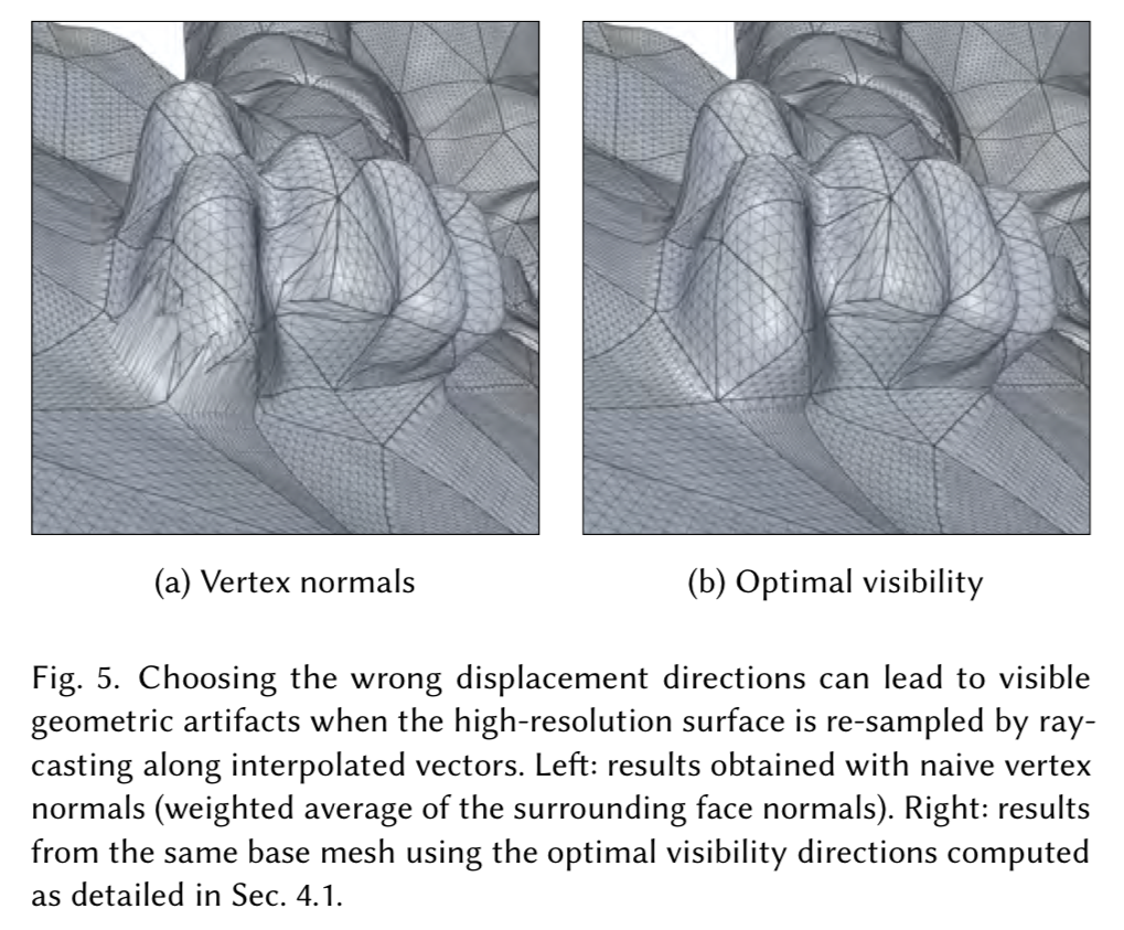
This paper has a lot to offer, but unfortunately, I have not finished reading it yet. (Hopefully in a future blog post.) However, I will try to point out something I have discovered so far. In order to pick a displacement direction for each vertex, the paper proposes a “visibility” metric, and try to maximize it per-vertex. Because as it turns out, simply using normal as the displacement direction can lead to geometric artifacts:
The paper tries to produce a suitable per-vertex displacement direction by employing a recursive method. Besides that, the paper tries to enforce several rules for the collapsed base mesh, including:
- Coarse base mesh: the base mesh must be coarse enough, so as to become memory efficient.
- Reprojectability: according to the paper, “to reproduce the input surface, the \(\mu\)-mesh must hit it (?) with the set of rays defined by \(\mu\)-mesh’s interpolated displacement vectors”. I interpret that as the original high-res input mesh must be reproducible by the subdivided & displaced base-mesh (\(\mu\)-mesh).
- Isotropy: the paper tries to avoid bad triangles from appearing during edge collapse. So it proposed a modified version of the quadric error method to try to prevent bad triangles from happening.
Further Readings
- Micro-mesh use case: https://github.com/NVIDIAGameWorks/Displacement-MicroMap-Toolkit/blob/main/mini_samples/dmm_displacement/README.md
- NVIDIA Displacement Micro-Map Toolkit: https://github.com/NVIDIAGameWorks/Displacement-MicroMap-Toolkit
- Micro-mesh basics slide: https://developer.download.nvidia.com/ProGraphics/nvpro-samples/slides/Micro-Mesh_Basics.pdf
- NVIDIA’s official website for micro-mesh: https://developer.nvidia.com/rtx/ray-tracing/micro-mesh
- NVIDIA’s baryfile repo (the micromap data structure): https://github.com/NVIDIAGameWorks/Displacement-MicroMap-BaryFile/
Sadly, without a 40 series GPU, the future of me actually able to run this thing is pretty bleak. But still, it’s pretty neat reading those. Toodles!
Comments