What is Perlin Noise?
To understand what Perlin noise is, we have to look at what regular noise and hash functions are first. Go on, give it a read. I will wait for you here. Alright. Have you read that? Cool. Now let’s proceed.
Proposed by Ken Perlin, Perlin noise is really similar to value noise. But instead of interpolating 1-dimensional noise values, Perlin noise instead interpolates the dot product of multi-dimensional noise values. In this way, it is much more chaotic (as a result, less blocky,) and the overall algorithm produces a smoother noise as a result.
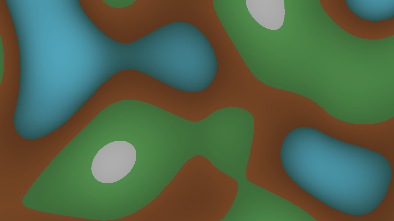
Perlin noise is widely used in terrain generation, textures, and basically everything rendering related. It is used to add detail to a lot of textures. It’s the building block of a mathematical world. Take a look at this terrain generation shader (that I wrote):
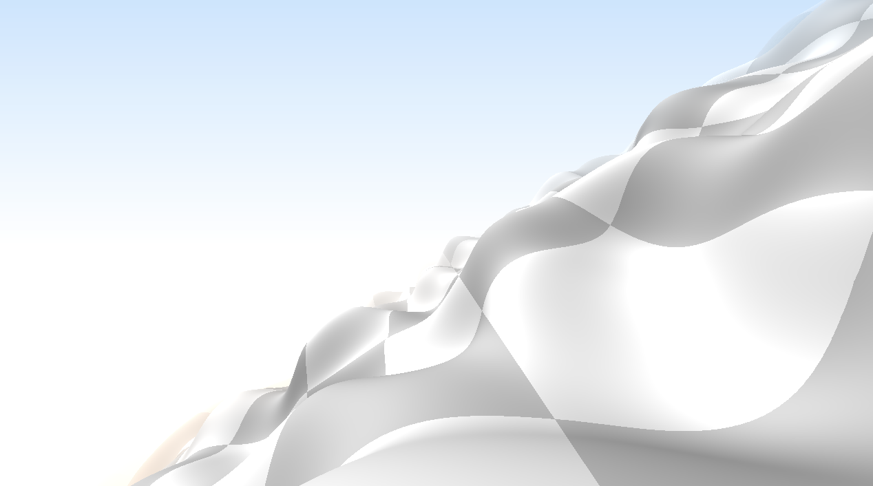
Or, this Perlin coaster ride, that I also wrote:
Perlin noise is also an instrumental first step in generating Inigo Quilez’s Clouds shader’s volume. This is how that looks like:

2D Hash Function
Since 2D Perlin noise interpolates 2-dimensional noise value instead of one, a vector hash function is needed. Not much is changed from the hash function, except this time it’s two dimensional.
vec2 rand2d(vec2 uv) {
    return fract(sin(vec2(dot(uv, vec2(12.34, 45.67)),
        dot(uv, vec2(78.9, 3.14)))) * 12345.67) * 2.0 - 1.0;
}
You can also write that as a matrix multiplication, as is the case of XorDev’s hash2d implementation. Once the 2D hash function is implemented, we can proceed to implement Perlin noise.
Perlin Noise Implementation
The recipe is as follows:
- Sample the four corners of the current cell (four 2-dimensional vectors)
- Evaluate the dot products of the sampled result and the vector of sample point \(p\) pointing towards the cell
- Interpolate the four results using cubic interpolation (or quintic)
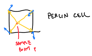
If you are a little bit puzzled about what the hell step 2 is about, the four dot product are the yellow arrows dotting with their respective corner’s blue arrows. Step 3 is then executed to interpolate those dot products and make the end result look smooth. Here’s how it looks like in GLSL:
float perlin(vec2 uv) {
    vec2 u = floor(uv);
    vec2 f = fract(uv);
    vec2 s = smoothstep(0.0, 1.0, f);

    vec2 a = rand2d(u);
    vec2 b = rand2d(u + vec2(1.0, 0.0));
    vec2 c = rand2d(u + vec2(0.0, 1.0));
    vec2 d = rand2d(u + vec2(1.0, 1.0));

    return mix(mix(dot(a, -f), dot(b, vec2(1.0, 0.0) - f), s.x),
        mix(dot(c, vec2(0.0, 1.0) - f), dot(d, vec2(1.0, 1.0) - f), s.x), s.y);
}
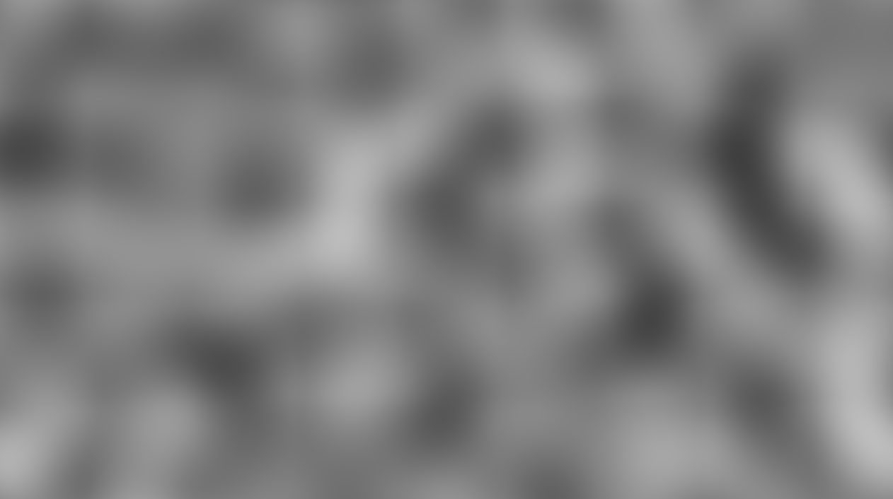
Since a dot product is involved, the end result of Perlin noise can be negative. In which case, a simple perlin(uv) * 0.5 + 0.5 should bring it back. Here’s how it it should look like:
Comments